
Research Project "Coupled Tape-Wound Cores”
Coupled-inductor configurations are proposed featuring high power densities based on two mechanisms i) using some high-performance magnetic material and ii) dc-flux cancellation to minimize cross-section of the core. Low Proximity Effect, HF EMI damping and mass manufacturability are regarded.
Auf einen Blick
| Kategorie | Beschreibung |
|---|---|
| Forschungsprojekt | Coupled Tape-Wound Cores |
| Leitung | Prof. Dr.-Ing. Christian Dick |
| Fakultät | Fakultät Informations- Medien und Elektrotechnik |
| Institut | Institut für Automatisierungstechnik |
| Beteiligte | Christian Dick, Patrick Deck |
| Fördermittelgeber | EFRE, MIWF NRW (Förderlinie NRW-Patentvalidierung) Aktenzeichen EFRE-0400028 |
| Laufzeit | 01/2016 bis 12/2017 |
1. Introduction
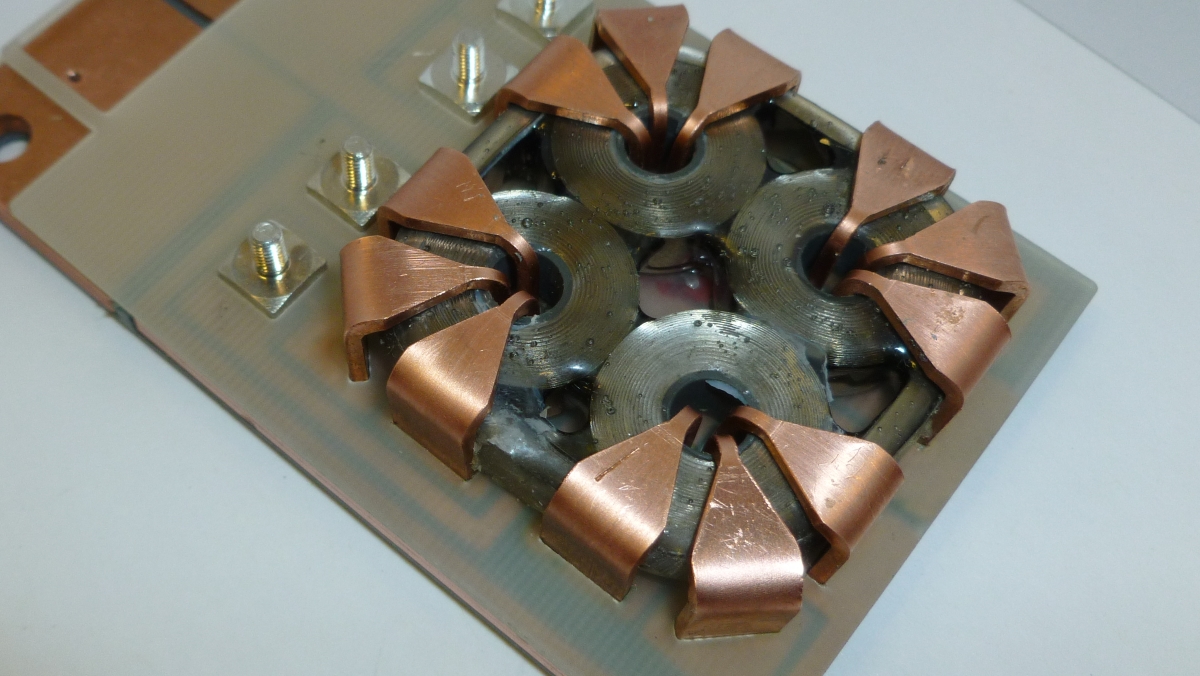
In case of high-current applications inverter-branches are in parallel to have feasible current carrying capability per phase. Compared to such interleaved converter solutions, the approach using coupled-inductors means no extra effort in terms of semiconductor, driver and current sensing. However, cost-intensive magnetics are minimized that far that it is also worth considering whether single-phase solutions should be substituted by the coupled approach. One example, a 48V-12V demonstrator is depicted in Figure 1.
In the subsequent chapters it is motivated why some of a high-performant soft magnetic material is chosen and how it is configured to take advantage of its properties. Furthermore, this article puts emphasis on the understanding and discussion of the behavior of our prototypes. Other designs with need for high power density at high currents (e.g. 400V-800V DC-converter) can be derived.
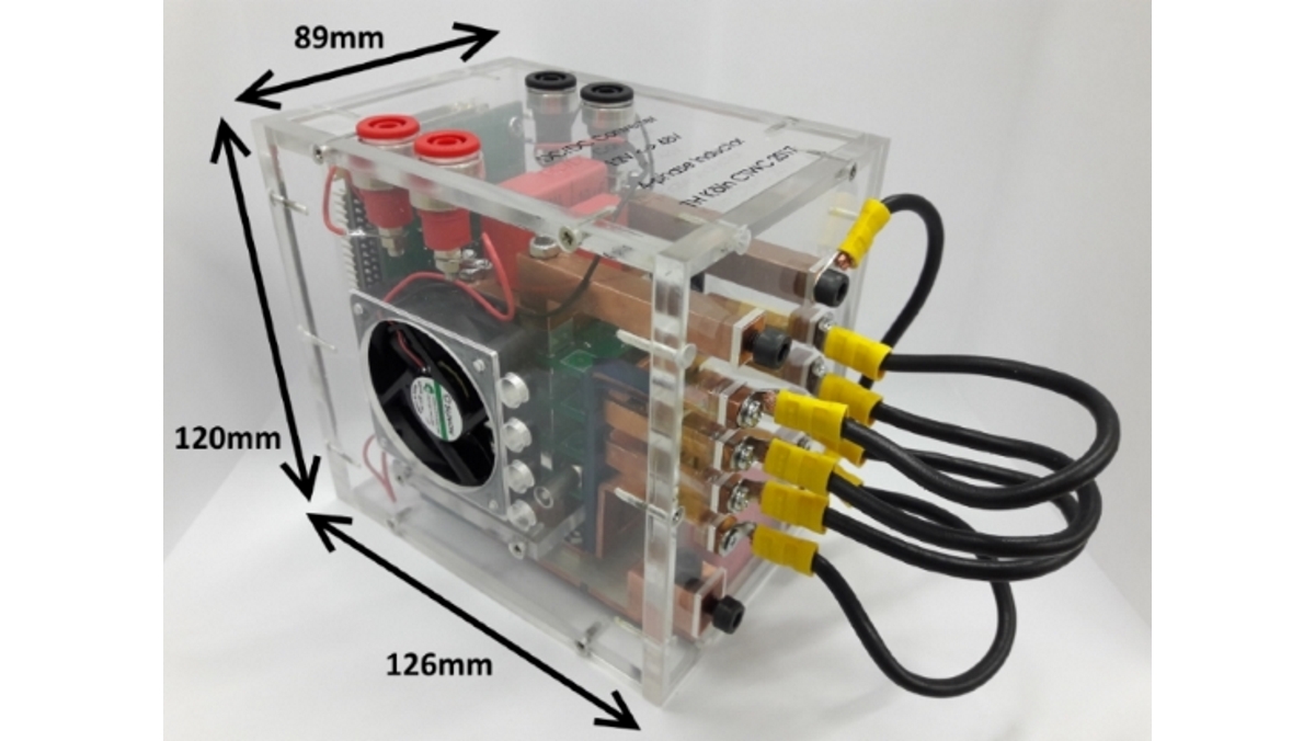
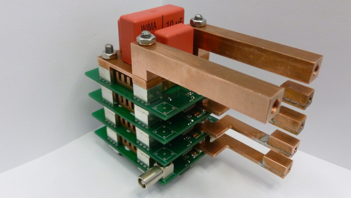
Fig 1: Four-phase coupled inductor
 0 / 0
0 / 0
Voltage = 48V, Current = 170A, Volume = 24cm^3 = 46.3 x 46.3 x 11.25mm^3 (overall outer cuboid inductor volume) (Bild: Patrick Deck, TH Köln)
 0 / 0
0 / 0
Voltage = 48V, Current = 170A, Volume = 24cm^3 = 46.3 x 46.3 x 11.25mm^3 (overall outer cuboid inductor volume) (Bild: Patrick Deck, TH Köln)
 0 / 0
0 / 0
Voltage = 48V, Current = 170A, Volume = 24cm^3 = 46.3 x 46.3 x 11.25mm^3 (overall outer cuboid inductor volume) (Bild: Patrick Deck, TH Köln)


2. Soft-magnetic core material at high peak-to-peak flux excitation
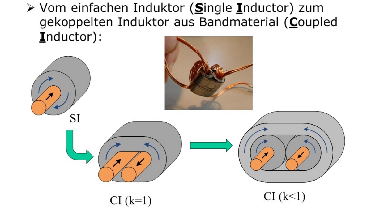
Nanocrystalline tape material is typically known for its high relative permeability such that it is often used in common-mode chokes. However, today it is possible to manufacture such material at low relative permeability (µr= 150 …. 2000) without loosing the high performance properties of the material, i.e. saturation flux density of 1,2 T and low losses [1][2]. Thus it is possible to basically store magnetic energy in the quasi-distributed airgap of tape-wound cores, featuring the big advantage of low proximity losses especially at high currents.
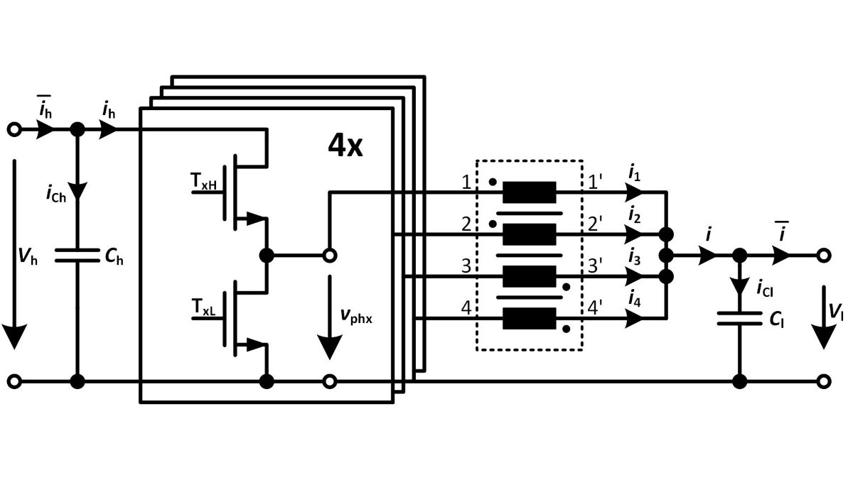
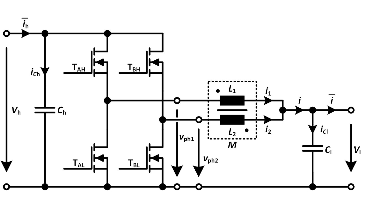
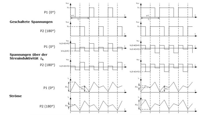
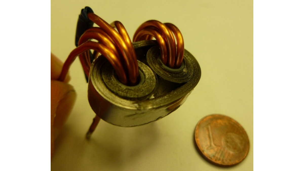
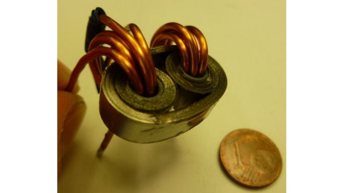
Discussing single-phase inductors, flux excitation is proportional to inductor current. In high-current applications coming with a significant amount of dc-current such tape-wound cores would result in an inductor operating at its saturation limit with a small ac-flux component, such that the thermal limit of the material is never reached. To really stress the material it would be beneficial to have a pure ac-flux at much higher peak-to-peak flux excitation and design the system to its thermal limitation. One mechanism to do this is using coupled inductors. For better understanding a two-phase inductor is depicted in Figure 2.
Principle sketch of a two-phase coupled inductor setup & self-wound core
 0 / 0
0 / 0
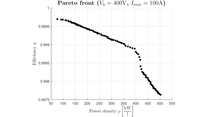
Voltage = 400V, Current = 100A, arbitrary duty cycle, SiC converter operating at 90 kHz, inner leakage-flux cores might be replaced by powder cores (Bild: Patrick Deck, TH Köln)
 0 / 0
0 / 0
Voltage = 400V, Current = 100A, arbitrary duty cycle, SiC converter operating at 90 kHz, inner leakage-flux cores might be replaced by powder cores (Bild: Patrick Deck, TH Köln)
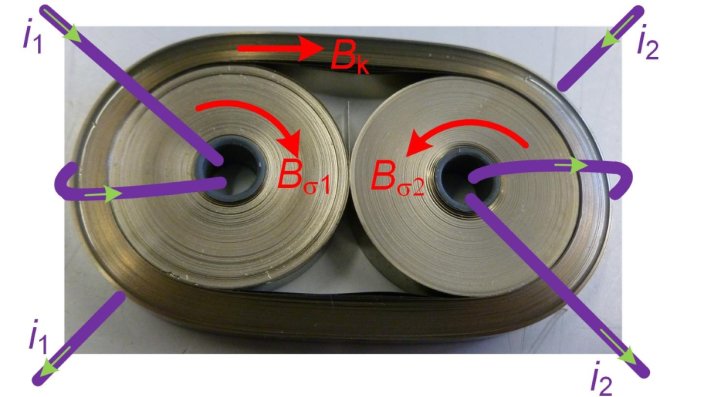
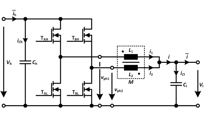
From the setup the subsequent proportionalities can be directly derived:
B_σ1 ~ i_1 leakage path phase 1
B_σ2 ~ i_2 leakage path phase 2
B_k ~ i_1 - i_2 coupling path
Thus, when both currents are controlled on the same dc-level, the coupling path is free of dc-flux, B_(k,dc)=0T. As a consequence, ac flux excitation B_(k,ac) may be chosen much larger without driving the material into saturation. It turns out that the most compact solution is given when the material is operated at its thermal limitation of 250 W/kg local losses.
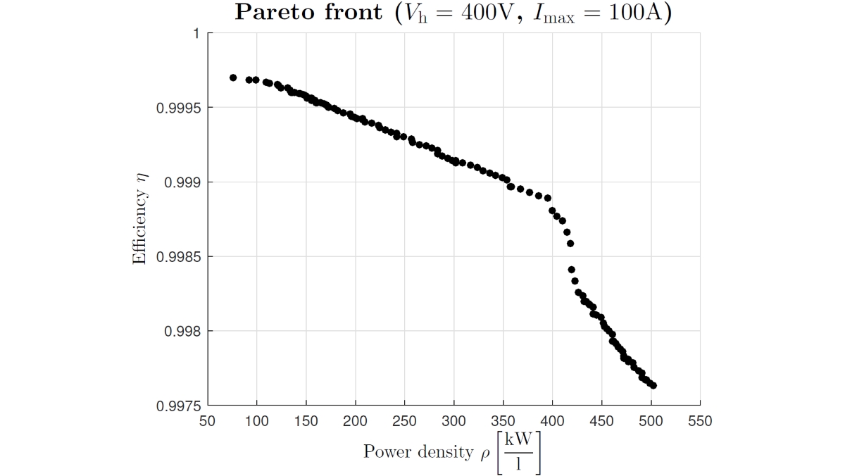
Designs based on pareto analyses were conducted. Various material probes of relative permeability between 160 and 1900 available in the lab were calculated, many boundary conditions such as thermal, saturation and various geometric limits, including the copper windings, were regarded. As a result the number of electrical turns, self-inductance and coupling coefficient together with their geometric properties were given. Furthermore, the relative permeability to be chosen for the leakage path and coupling path respectively was determined.
It turns out that the analytical reluctance model of the coupled inductors fits well to the measurements using impedance analyzers. This is traced back to the obvious predominant direction for conducting the flux within the wounded tapes.
3. 400V/100A two-phase inductor design
This design based on the principle of Figure 2 was optimized for the inductor core as first demonstrator [3]. Output current could be increased up to 110A without facing thermal or saturation problems. The inductor is placed in the laboratory without casing and without forced convection at room temperature. At full duty cycle, power density is determined at 110 A in the lab at 297kVA/ltr.
") Equation 4: Calculation of power density (2-phase CI)
(Bild: Christian Dick, TH Köln)
Equation 4: Calculation of power density (2-phase CI)
(Bild: Christian Dick, TH Köln)
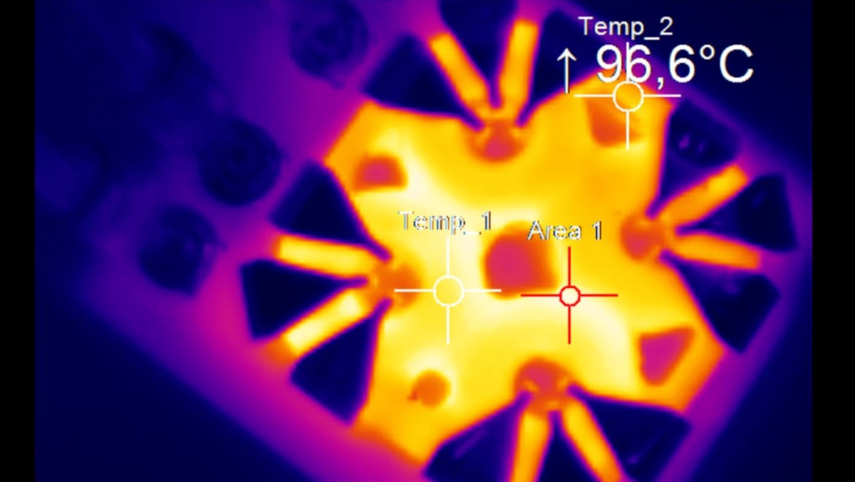
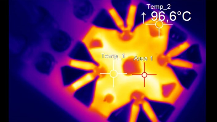
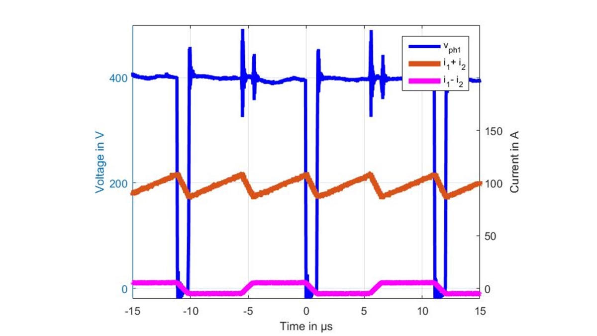
Fig 3: Results of two-phase converter
 0 / 0
0 / 0
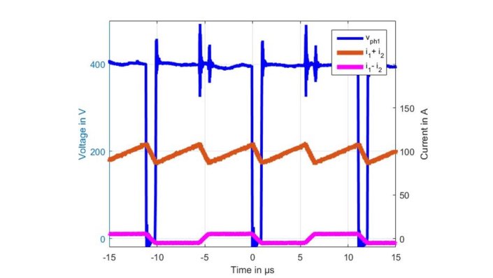
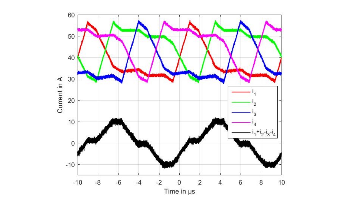
Operation of the the two-phase coupled inductor @ P = 37kW and d=0.93 (Bild: Patrick Deck, TH Köln)
 0 / 0
0 / 0
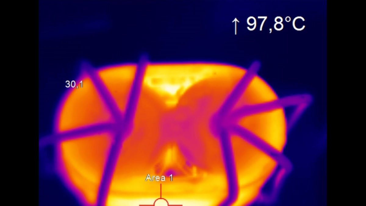
Thermal image at critical duty cycle of d = 0.5 (Bild: Patrick Deck, TH Köln)
 0 / 0
0 / 0
Result of two-phase pareto analysis (Bild: Patrick Deck, TH Köln)
 0 / 0
0 / 0
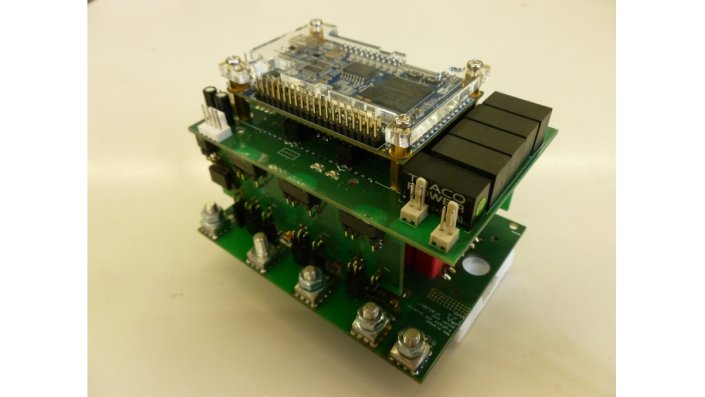
SiC converter (Bild: Patrick Deck, TH Köln)
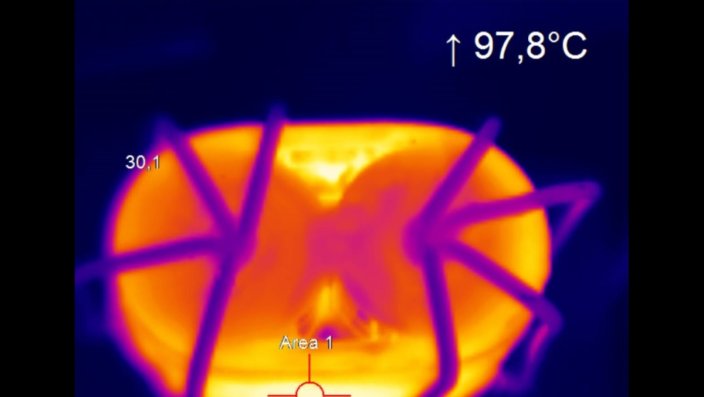
The infrared image was taken at duty cycle of d=0.5, since then stress on the magnetic core is maximum, especially for the coupling path. However, since 160°C is still feasible for the core material, there is much headroom for elevated ambient temperatures.
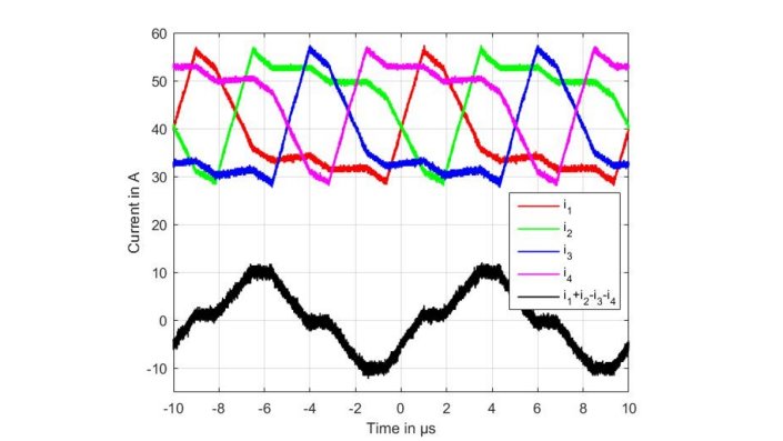
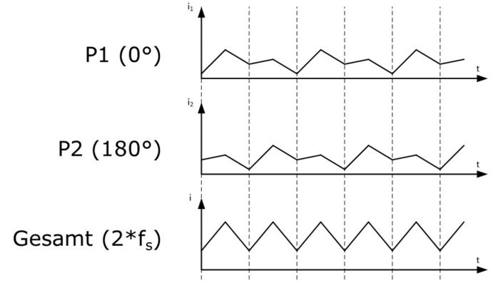
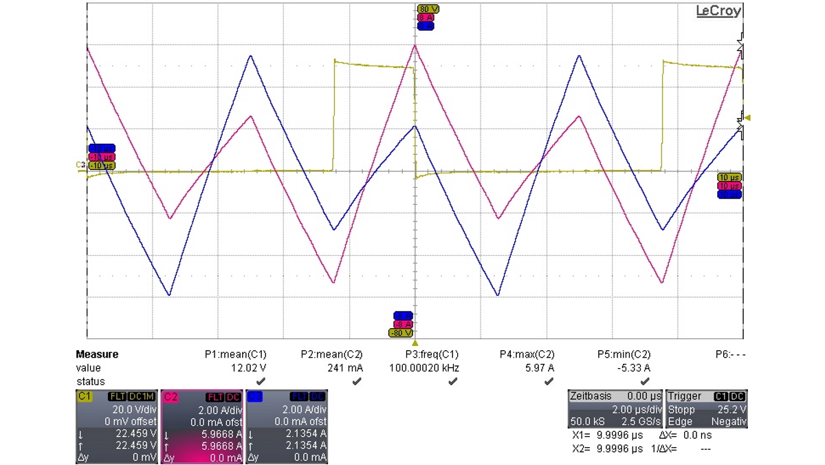
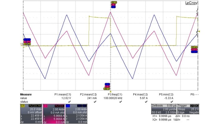
Both currents have the same dc-level up to 55A and an ac-ripple of max. 30App. The currents i_1, i_2 and (i_1+i_2) show strong harmonic components at 2*f_s. However, this harmonic cancels out in (i_1-i_2) as modeled and also proven Figure 3, where the current probe is connected correspondingly. Thus, the coupling path is only stressed at f_s. In the current design this results in maximum flux densities of:
B_(σ,dc)=764 mT B_(σ,ac,pp)=472 mT @ 180kHz
B_(k,dc)=0 T B_(k,ac,pp)=1,44 T @ 90kHz
Latter number is considered enormous in conjunction with the steady state thermal image. The overall converter using SiC MOSFETs showed an efficiency of 98,7%±0,98%, about 100 W losses are traced back to the inductor.
There is room for improvements, pareto analysis shows even higher compactness when relative permeability could even be reduced for the leakage path (125 instead of 160) and the coupling path (780 instead of 900). Such material can be produced, optimization potential is given.
4. 48V/170A four-phase inductor design
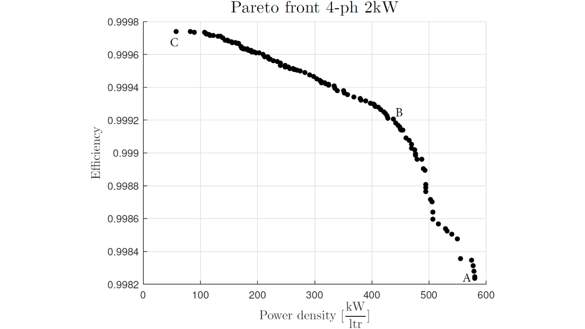
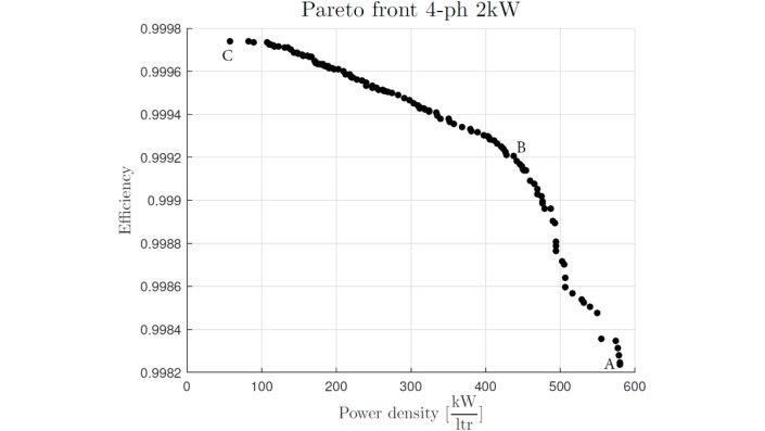
A second GaN-based demonstrator as depicted in Figure 1 is designed based on pareto analysis. All phases operate 90° phase-shifted at 100kHz, a current controller shares the load equally. Many of the indicated effects in the two-phase system are valid as well in this four-phase configuration [4]. The system is capable of driving the full duty cycle, however, in the application of mild hybrid vehicles with 48V-12V DC-DC converters 14V is considered as maximum output voltage. A high power density of 99kVA/ltr is demonstrated at high flux excitation:
") Equation 7: Calculation of power density (4-phase CI)
(Bild: Christian Dick, TH Köln)
Equation 7: Calculation of power density (4-phase CI)
(Bild: Christian Dick, TH Köln)
B_(σ,dc)=620mT B_(σ,ac,pp)=760mT
B_(k,dc)=0 T B_(k,ac,pp)=1,18T @ 100kHz
Fig 4: Results of four-phase converter
 0 / 0
0 / 0
Operation of the four-phase coupled inductor here @ d = 0.17 (e.g. 53V <> 9V) (Bild: Patrick Deck, TH Köln)
 0 / 0
0 / 0
Overall converter package (Bild: Patrick Deck, TH Köln)
 0 / 0
0 / 0
Result of pareto analysis (Bild: Patrick Deck, TH Köln)
 0 / 0
0 / 0
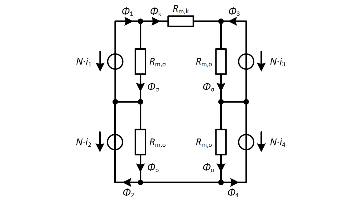
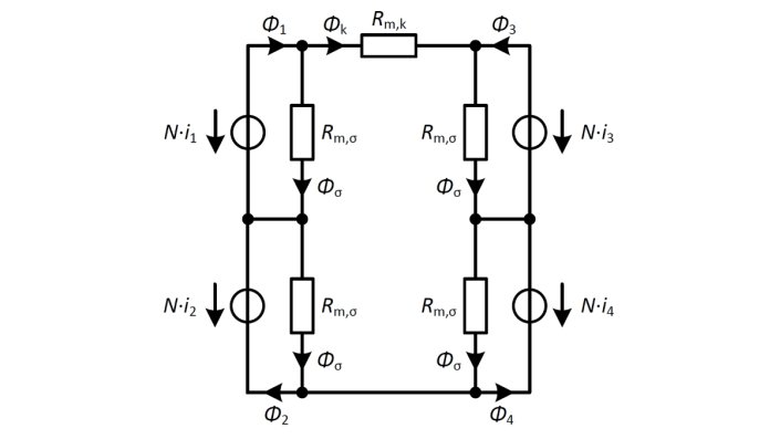
Four-phase reluctance model (Bild: Patrick Deck, TH Köln)
 0 / 0
0 / 0
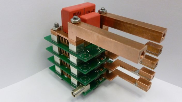
Four-phase power stage (Bild: Patrick Deck, TH Köln)
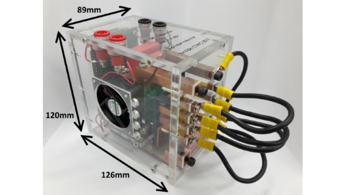
Overall efficiency of the converter is up to 96,5%, losses being traced back to the inductor are below 20 W. Under full load conditions the 24 cm^3 inductor (outer cuboid volume) is thermally feasible, see also Figure 1. The maximum temperature of about 100°C, measured in the lab without casing at room temperature without forced convection or cooling plate, is basically too low. In a future design maximum local losses should be limited to higher numbers than 250W/kg (current design). Again, choosing material with slightly adapted relative permeability is basically another optimization potential.
5. Conclusions and outlook
Two very compact coupled inductors were presented for high-current applications. The demonstrated power densities are higher than all solutions known to the authors as state of the art (partly multiple).
- Demonstrated solutions are thermally feasible: There is some headroom for further shrinking
- Efficient inductor: Low proximity losses due to quasi distributed airgap in high current inductor
- Mass producibility: Single copper-turns can be welded automatically in lead frame
- HF-EMI (both DM and CM) is dampened due to eddy currents in the tape material (not quantified yet)
- Cost reduction potential: Major contributor for gaining such high power densities is using some high performant low-µ nanocrystalline tape material in the coupling path at extreme flux excitation. The inner leakage path with elevated dc-flux offset may be realized by powder cores
- Many other designs with need for power density at high currents (e.g. 22kW 400V-800V DC onboard-charger) can be derived, tool is available
6. References
[1] C. Polak - Vacuumschmelze GmbH & Co.KG: private communication and “Nanocrystalline Materials for High Frequency Applications”, Invited Talk, 4th International Conference on Superconductivity and Magnetism- ICSM2014, 27.4.-2.5.2014, Antalia, Turkey, 2014
[2] Magnetec GmbH: Datasheet information “Nanoperm® LM Cores for DC biased applications” (www.magnetec.de, Download 29.05.2019)
[3] Patrick Deck, Christian P. Dick: High power density dc/dc-converter using coupled inductors. In EPE ECCE Europe 2017, Sept. 2017, ISBN: 9789075815276
[4] Patrick Deck, Christian P. Dick: Ultra compact 2kW 12V-48V converter using a 4-phase coupled inductor; PCIM Europe 2018; International Exhibition and Conference for Power Electronics, Intelligent Motion, Renewable Energy and Energy Management; June 2018 Nuremberg Germany, ISBN: 978-3-8007-4646-0
The English part of this website was first published in Bodo's Power Systems, issue 08/2019.
Forschungsprojekt Coupled Tape-Wound Cores
In diesem Forschungsprojekt werden neuartige gekoppelte Induktoren aus eisenbasierten, nanokristallinen Bandmaterialien erforscht, aufgebaut und schließlich demonstriert. Die gekoppelten Induktoren sollen mit einer Inverter-Vollbrücke einen materialarmen Ersatz für die klassischen hartgeschalteten Inverterhalbbrücken mit induktivem Abgang bilden.
Das erklärte Ziel des Projektes ist es, eine hartgeschaltete 2-phasige DC/DC-Wandler Topologie mit einer gekoppelten Induktivität sowohl mathematisch zu modellieren als auch das Modell in einem zweiten Schritt durch Funktionsmuster und Prototypen zu validieren. Das Ergebnis soll eine kostengünstige, material- und volumenreduzierende Technologie sein und so einen Beitrag für kompaktere Leistungselektroniken in Standardanwendungen bilden.
 Voltage = 400V, Current = 100A, arbitrary duty cycle, SiC converter operating at 90 kHz, inner leakage-flux cores might be replaced by powder cores
(Bild: Patrick Deck, TH Köln)
Voltage = 400V, Current = 100A, arbitrary duty cycle, SiC converter operating at 90 kHz, inner leakage-flux cores might be replaced by powder cores
(Bild: Patrick Deck, TH Köln)
Analytische Berechnung der Volumeneinsparung durch gekoppelte Induktivitäten
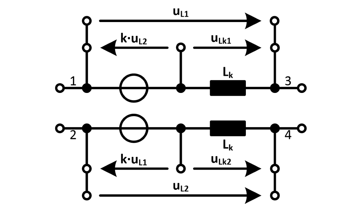
Im ersten Schritt des Projekts wird die Mathematik der gekoppelten Induktivitäten ausgearbeitet. Die Modellierung über ein elektrisches sowie magnetisches Ersatzschaltbild führt zu einem Volumenvergleich der gekoppelten Induktivität mit der einfachen Induktivität, welcher die klaren Volumenvorteile in einem Diagramm aufzeigt.
Analytische Berechnung
 0 / 0
0 / 0
Der Weg vom einfachen Induktor zum Tape-wound core (Bild: Patrick Deck, TH Köln)
 0 / 0
0 / 0
Ersatzschaltbild CI (Bild: Patrick Deck, TH Köln)
 0 / 0
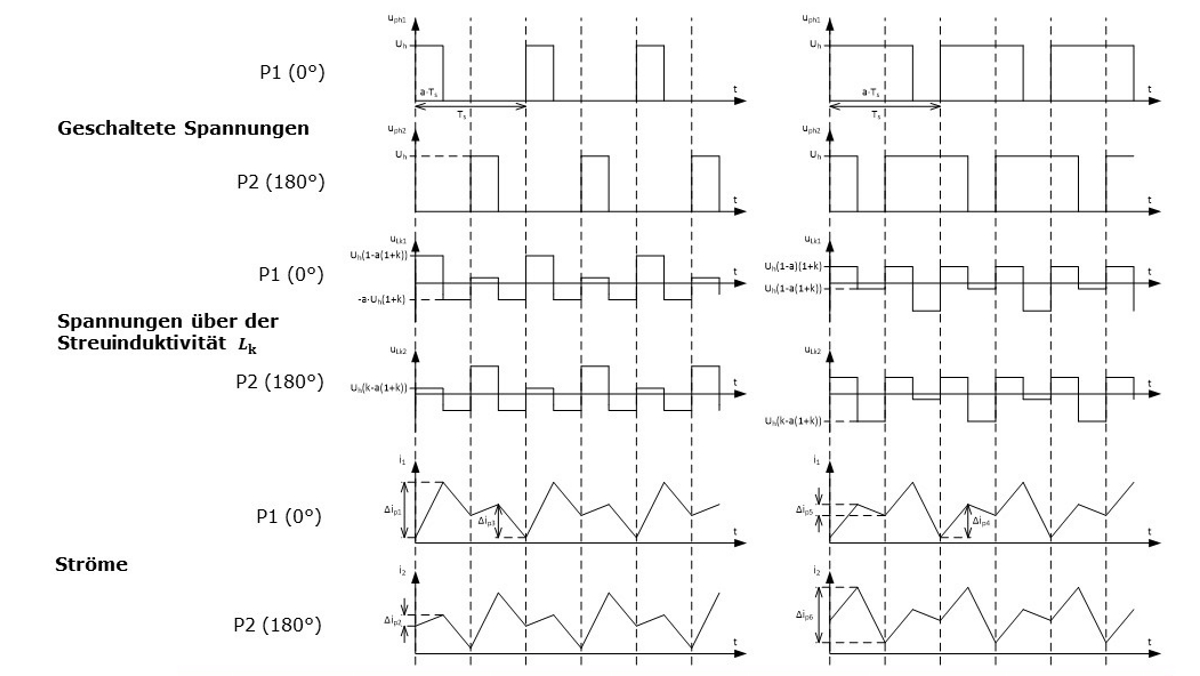
0 / 0
Die Stromformen im CI (Bild: Patrick Deck, TH Köln)
 0 / 0
0 / 0
Der Gesamtrippel besitzt die doppelte Schaltfrequenz (Bild: Patrick Deck, TH Köln)
 0 / 0
0 / 0
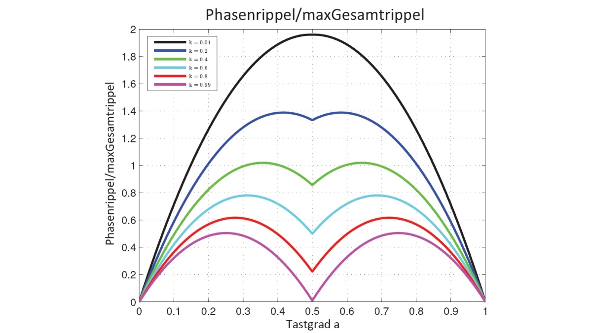
Der Phasenrippel im 2 phasigen CI abhängig von Tastgrad und Kopplungsfaktor bezogen auf den maximalen Gesamtrippel (Bild: Patrick Deck, TH Köln)
 0 / 0
0 / 0
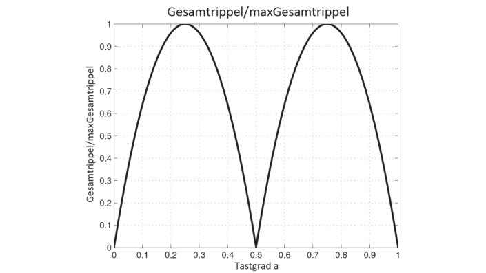
Der Gesamtrippel im 2 phasigen CI abhängig vom Tastgrad bezogen auf den maximalen Gesamtrippel (Bild: Patrick Deck, TH Köln)


 Der Volumenvergleich zwischen einfacher und gekoppelter Induktivität aufgetragen über dem Verhältnis Stromrippel zu Gesamtstrom
(Bild: Patrick Deck, TH Köln)
Der Volumenvergleich zwischen einfacher und gekoppelter Induktivität aufgetragen über dem Verhältnis Stromrippel zu Gesamtstrom
(Bild: Patrick Deck, TH Köln)
Aufbau von Mustern und Demonstratoren mit hoher Leistungsdichte >40kW/l
Der zweite Schritt stellt den Aufbau von Demonstratoren dar, welcher im Gegensatz zu herkömmlichen einphasigen Ferrit-Aufbauten eine sehr hohe Leistungsdichte aufweisen soll. Für die Auslegung und den Test werden mit Hilfe der mathematischen Modelle Optimierungen durchgeführt.
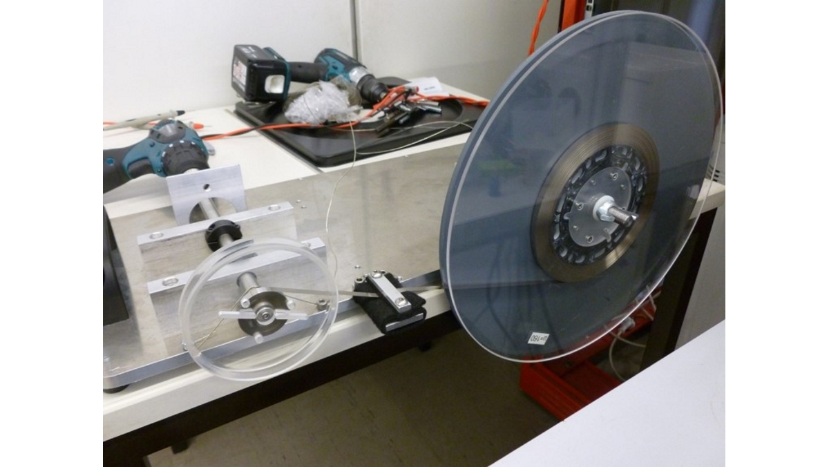
Die Herstellung der Induktivitäten erfolgt über eine eigens entwickelte Wickelmaschine, welche eine direkte Induktivitätsmessung der Kerne ermöglicht. Um genügend Leistung bereitstellen zu können, wird ein dreiphasiger Prüfstand aufgebaut, welcher eine Leistung von bis zu 60kW aufweist.
Im letzten Schritt wird mit den bestehenden Erkenntnissen ein kompakter Konverter aufgebaut, der bidirektional in einem Tastgradbereich von 0…1 Spannungen einstellen kann. Die maximale Spannung beträgt hier 400V bei einem maximalen Gesamtstrom von 100A. Bei einem Bauvolumen von ca. 1l beträgt die Leistungsdichte in etwa 40kW/l.
Hardwareaufbauten und experimentelle Ergebnisse
 0 / 0
0 / 0
Gekoppelte Induktivität für einen 48/12V Wandler (Imax=50A, Schaltfrequenz= 100kHz) (Bild: Patrick Deck, TH Köln)
 0 / 0
0 / 0
Wickelmaschine zur Fertigung von gekoppelten Induktivitäten aus Bandmaterial (Bild: Patrick Deck, TH Köln)
 0 / 0
0 / 0
Test 48/12V Wandler (Bild: Patrick Deck, TH Köln)

") Gefördert aus Mitteln des Europäischen Fonds für regionale Entwicklung (EFRE)
(Bild: MBWSV Nordrhein-Westfalen)
Gefördert aus Mitteln des Europäischen Fonds für regionale Entwicklung (EFRE)
(Bild: MBWSV Nordrhein-Westfalen)